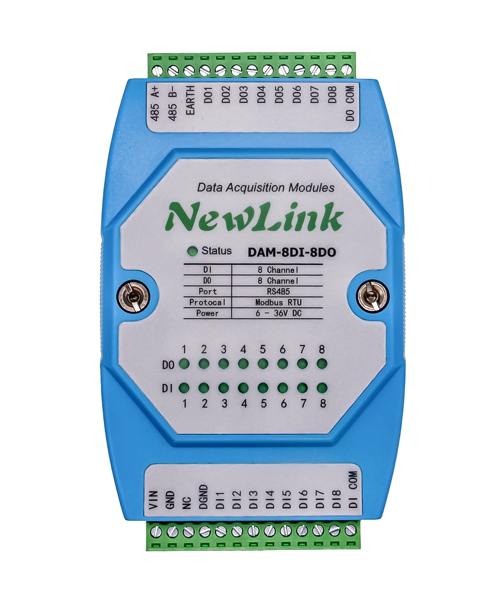
DAM-8DI-8DO
RS-485 interface, 8 digital inputs, 8 digital outputs
Overview
- Industrial 8-channel digital input + 8-channel digital output module.
- RS-485 interface and standard Modbus RTU protocol.
- Bidirectional opto-isolation on the input side; supports dry contacts and active wet contacts (NPN / PNP).
- Outputs use Darlington open-collector drive with opto-isolation; 500 mA per channel.
- Supports linkage, cycle, toggle, delay, flash on/off, and other output control modes.
- Dual isolation on the communication path with fuse、TVS and gas discharge tube protection.
- Stable and reliable for demanding industrial applications.
Specifications
| Item | Details |
|---|---|
| Power | 6–36 V DC |
| Interface | RS-485 |
| Baud rates | 4800, 9600, 19200, 38400, 57600, 115200, 128000, 256000 |
| Default format | 115200, N, 8, 1 |
| Digital outputs | 8 channels, 5–36 V, NPN Darlington open-collector, 500 mA per channel |
| Digital inputs | 8 channels, 5–30 V; dry contact / active input (NPN or PNP) |
| Protocol | Standard Modbus RTU |
| LED | STA: solid on in Bootloader mode; slow blink when running; fast blink during communication |
| Dimensions | 121 × 72 × 34 mm |
Hardware interface
| Function | Pin | Description |
|---|---|---|
| Power DC 6–36 V | VIN | Positive |
| GND | Negative | |
| Unused | NC | Unused pin; leave floating |
| Communication | RS485 A+ | RS-485 A |
| RS485 B- | RS-485 B | |
| EARTH | RS-485 ground / earth | |
| Digital input | DI COM | Input signal common |
| DGND | Digital ground | |
| DI1–DI8 | Channels 1–8 digital inputs | |
| Digital output | DO COM | Clamp diode anode; use with inductive loads such as relays |
| DGND | Digital ground | |
| DO1–DO8 | Channels 1–8 digital outputs |
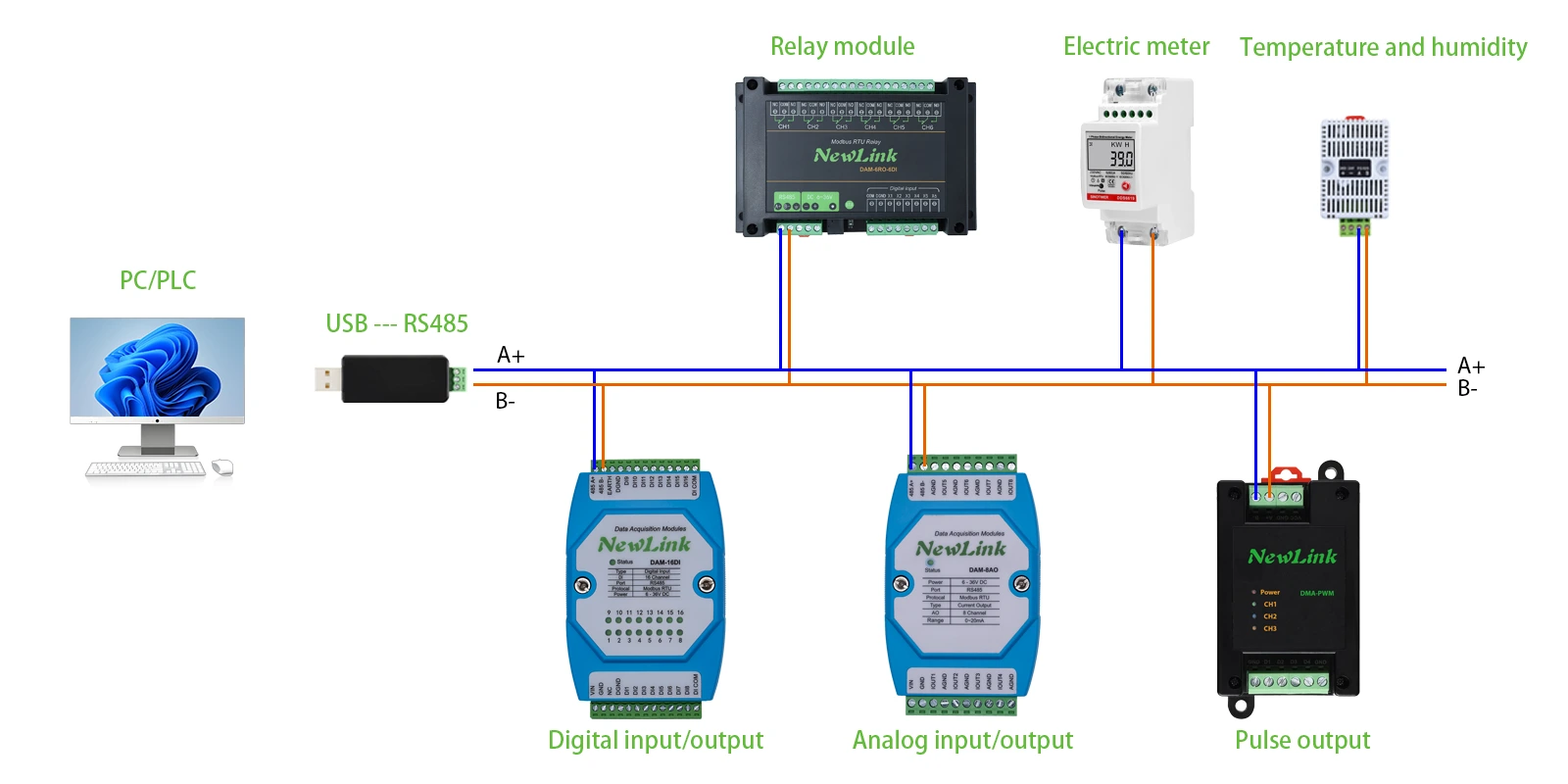
RS-485 bus wiring
Most PCs have no RS-485 port. Use a USB-to-RS485 adapter; connect A to the module A terminal and B to B. For multiple devices, use twisted-pair shielded cable in a daisy-chain topology.
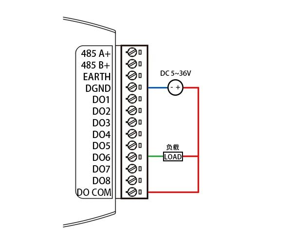
Digital output wiring
Outputs are NPN Darlington open-collector: connect the load between the external supply positive and the corresponding DOx; connect DGND to the external supply negative. For inductive loads, add a freewheeling diode and connect DO COM to the supply positive.
When the output is OFF, DOx is high-impedance, the load is disconnected, and the LED is off. When ON, DOx is pulled low, the load is energized, and the LED is on.
Digital input wiring
DI1–DI8 are the 8 input channels; DGND is the signal ground. DI COM is the input common—it may be left floating, tied to supply positive, or tied to supply negative. Power may come from the module supply or an independent source.
- Floating: dry contact (passive) input
- Tied to supply +: low-level trigger, NPN wet / active input, 5–30 V DC
- Tied to supply −: high-level trigger, PNP wet / active input, 5–30 V DC
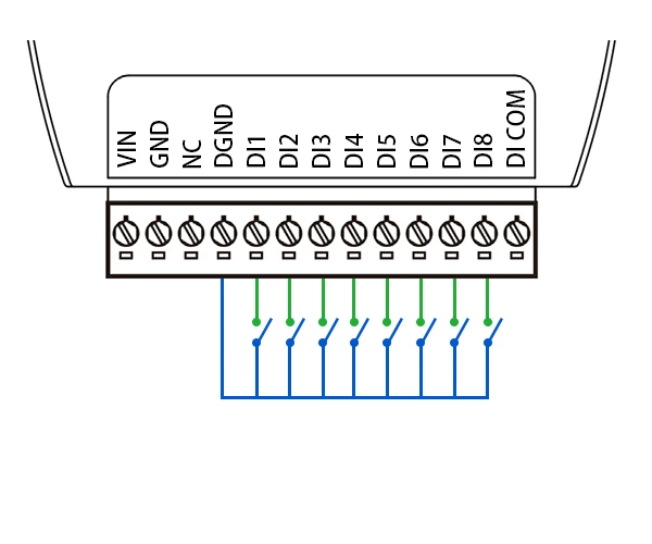 Dry contact wiring | 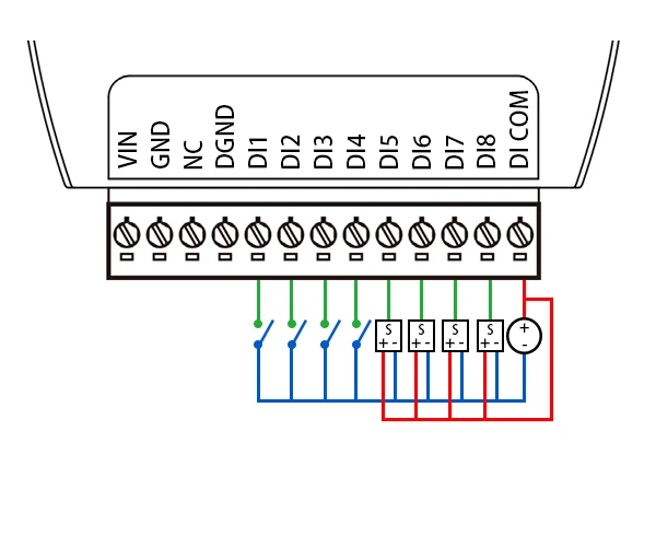 NPN active (wet) input wiring | 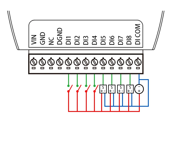 PNP active (wet) input wiring |
Operation demo
Two tools are shown below. Either works for first bring-up; the web serial assistant is recommended for a quick start.
- Web serial assistant: no install; full frame display and parsing; less intuitive for register data.
- Modbus Poll: direct register access; easier to read output/input states; frames are not fully shown.
- Serial assistant
- Modbus Poll
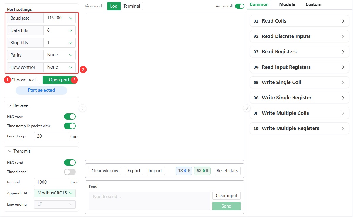
- Open the serial debug tool, select the COM port, set 115200 N 8 1, and open the port.
- Enable hex display and hex send, set checksum to ModbusCRC16, send
01 05 00 00 FF 00. CH1 output should turn on and echo the frame.
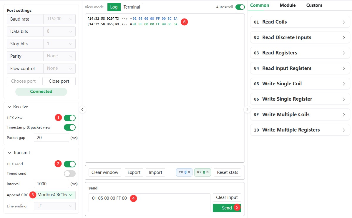
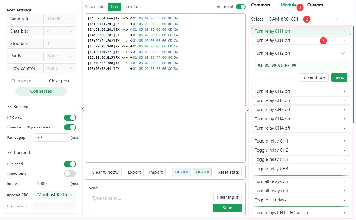
- Use Module commands on the right to pick the module model and send preset commands, or expand entries to edit before sending.
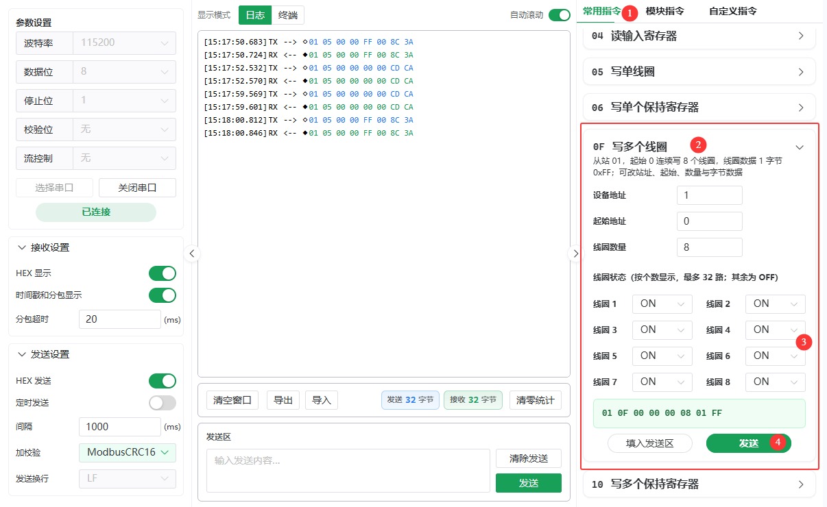
- Common commands builds Modbus function-code frames from parameters.
- Install Modbus Poll and open it.
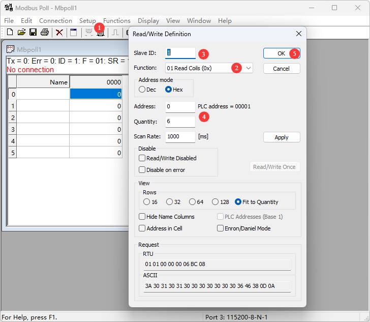
- Setup → Read/Write Definition: set Slave ID, Function
01 Read Coils, Quantity to the actual channel count, then OK.
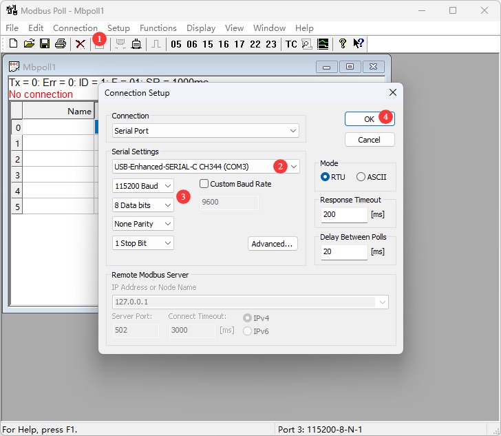
- Connection → Connect Setup: Serial Port, select COM port, 115200 N 8 1, OK.
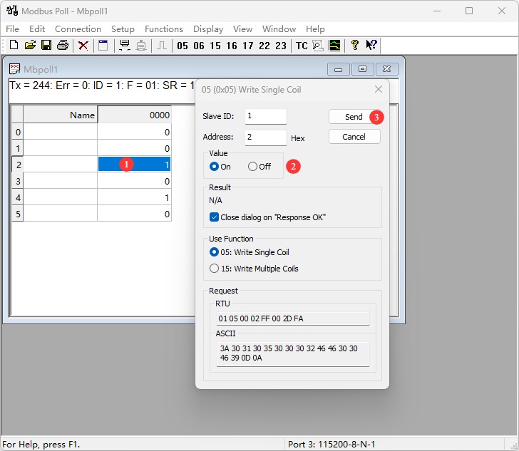
- After a successful connection, output states are shown. Double-click a channel value, choose On or Off, then Send to control that output.
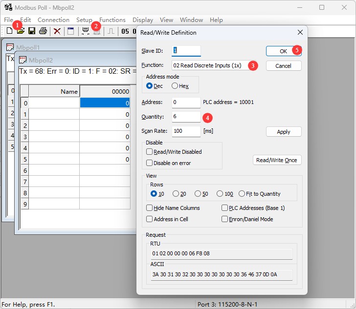
- File → New, then Setup → Read/Write Definition: set Slave ID, Function
02 Read Discrete Inputs, Quantity to the actual channel count, Scan Rate 100 ms, then OK.
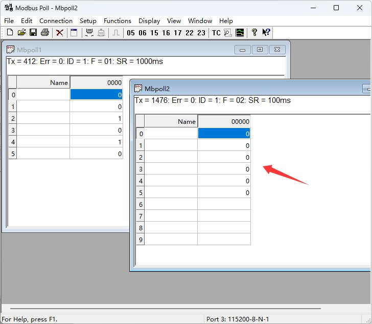
- Window 2 shows digital input states; changing an input updates the corresponding value.
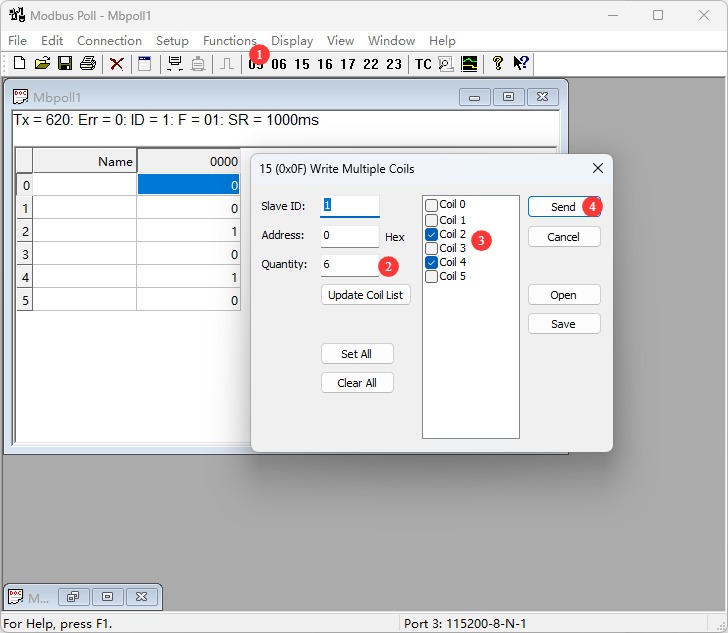
- Functions → 15: Write Multiple Coils: set start Address, Quantity to the actual channel count, set each channel state, Send. On success, outputs change and the window shows Response ok.
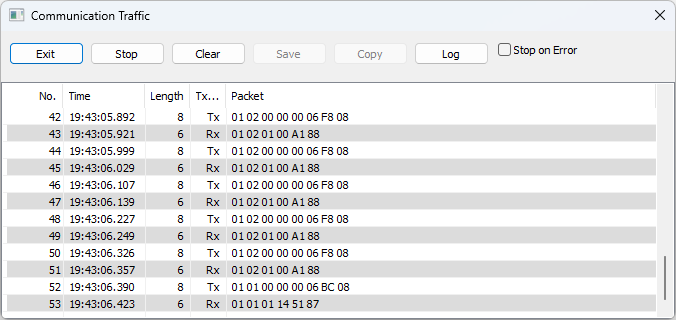
- Display → Communication shows raw TX/RX data.
Resources
Documentation
- Modbus protocol overview
- Modbus specification (Chinese PDF)
- Modbus Application Protocol (English PDF)